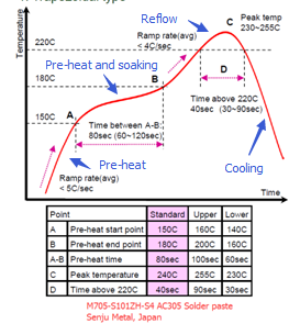
▪ Pre-heat zone (from room temperature to 150°C)
◦Solder paste collapse -- ramp up too fast
The solvent in flux cannot vapour thoroughly, so the viscosity of the solder paste will be decreased and cause the paste collapse
◦Soldering ball -- ramp up too fast
The solvent in flux vapours out too fast, causing some tiny paste areas to separate from the major paste area and forming individual solder balls around the component.
◦Solder splash – ramp up too fast
Same as soldering ball.
◦Poor wetting – ramp up too slow
Solder paste is oxidizing if the pre-heat too long.
▪ Pre-heat and soak zone (from 150°C to 180°C)
◦Tombstone -- ramp up too fast
The PCB and components didn’t get an even heat up.
◦Void -- ramp up too fast
The solvent in flux escaped too quickly.
◦Poor solder joint fillet -- ramp up too slow
The flux lost its activity once it stayed soaking too long.
▪ Reflow zone (above 217°C ~220°C for SAC305 solder paste)
◦Component damaged – peak temperature is too high
Once the peak temperature is over 260°C and stays there for more than 10 sec, most of components will be damaged.
◦Cool solder -- peak temperature is too low or time too short
The peak temperature should be 20~25°C higher than the solder liquid point and remains there for 30~90 seconds.
▪ Cooling zone (below 217~220°C after reflow)
◦Components crack -- cooling down too fast
Components experienced thermal shock outside of their specifications.
◦Increase component’s fatigue risk –cooling down too slow
The slow cooling can easily lead to an excess amount of intermetallic compounds and produce larger crystal particles together in soldering joint, reducing the fatigue strength.


