What is the function of capacitor?
When the capacitor is connected to the DC power supply, it accumulates power and continues to supply power for a while after the power is turned off. In other words, the capacitor acts like a rechargeable battery that can store or release electrical energy. This charging or discharging process is very fast, but several resistors can be used to limit its discharge rate, so that in many electronic circuits, capacitors are used as the original for time control.
In addition, the capacitor can also transmit pulse or electrical noise, alternating current, audio signals or other forms of waves to block the DC power supply. This feature allows the resistor to be used to smooth out the potential of the power supply output, remove extreme values in the signal to prevent improper excitation in the digital line, adjust the frequency response of the audio line, or need to connect to the line. Prevent originals that are directly transmitted by direct current.
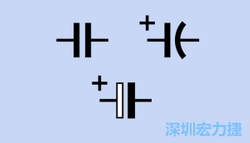
The symbol of the capacitor on the circuit diagram is shown in the right figure. The upper left corner is a non-polar capacitor, while the other two symbols represent the need for a polar capacitor. The direction is as shown. The following illustration is more prevalent in Europe, but what is confusing is that the symbol of the non-polar capacitor can also be used to indicate the polarity capacitor, as long as the + symbol is added; while the symbol of the polar capacitor is sometimes not + Symbol, but it still indicates the need to use a polar capacitor.
What is the principle of operation?
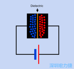
In its simplest form, a capacitor is a two-piece plate, each with a wire connected to a DC power supply. There is a thin barrier between the two plates, called a dielectric, which is usually solid or pasty, but sometimes it can be liquid, gel, gas or vacuum.
Most of the capacitor plates are made of a thin metal film or a metal-plated plastic film. In order to minimize the volume of the capacitor, the film may be rolled into a small cylindrical shape or a few layers of flat film. Stack.
The electrons from the power supply tend to move toward the film of the negative electrode and tend to repel electrons from the other side of the film. This process can also be understood as making a hole or attracting a positive charge on another board. When the capacitors are unplugged, because they attract each other, the opposite charge on the board will exist in a balanced manner, but after a long time, the voltage will slowly disappear and leak through the dielectric or other piping.
Many capacitors are non-polar, which means they are not sensitive to polarity, but the electrolyte or tank capacitor is connected in the direction of the DC power supply. If one conductor is longer than the other, it must be "positive". A wire, if marked or bent on a wire, represents a "negative" wire. Tan resistance has a + symbol to indicate the positive pole.
In addition, the arrow on the side of the capacitor usually refers to the end of the "negative cathode". If the capacitor body is an aluminum cylinder and a bipolar wire, one end of the wire will have an insulating material disk, and the other end wire will Connect the circular side of the capacitor body. In this case, the section with the insulating disc must be "more positive" than the other end.
The capacitor array indicates that more than one capacitor is internally separated from each other, connected through an external material, sometimes soldered in the form of a surface adhesion, and sometimes a dual-inline package (DIP) or a single-row package ( Single-inline package, referred to as SIP) in-line wafer form connection. As for the internal parts connection form, it can be divided into three types: independent, common bus system and bilateral public bus system. In theory, separate forms of connections should be referred to as capacitor arrays, but in practice these three forms of assembly are referred to as capacitor networks.
How many types it has?
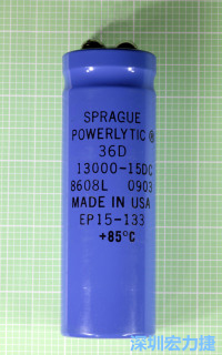
Electrolytic capacitors are relatively inexpensive, compact, and can find large-capacity specifications that make these capacitors very common in consumer electronic materials, especially for power supplies. Moreover, if the electrolytic capacitor is used for a long time, its ability to accumulate electricity will increase. The dielectric efficiency of the thick material in this capacitor will increase after the current is applied, but if it is not used for several years, it will be killed if there is an electrolytic capacitor. After ten years, it may still be possible to energize between the two wires after connecting the circuit.
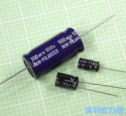
1.Bipolar electrolytic capacitors contain two parallel electrolytic capacitors in a single package. The heads are connected to the tail and have opposite polarities. Therefore, this combination can be applied to DC devices with voltage fluctuations of up to 0 volts. It has two electrolytic capacitors juxtaposed. The polarity of the capacitor housing may be labeled BP (bipolar, bipolar) or NP (nonpolarized, non-polar), it can also be applied to audio lines, in which case the polar capacitor is usually Not applicable, and non-polar electrolytic capacitors are also cheaper than other non-polar capacitors. However, it cannot avoid the disadvantages common to electrolytic capacitors.
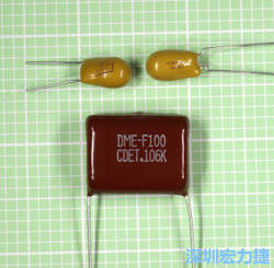
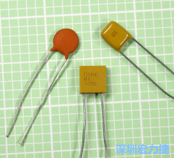
2.Tan capacitors are very small, but they are relatively expensive and very sensitive to voltage fluctuations. If the polarity is wrong or the fluctuation is too large, it may cause damage. Usually, the tantalum capacitor is covered with a layer of epoxy resin, and the electrolytic capacitor is not placed in the aluminum shell. Therefore, the dielectric is not so easy to evaporate or dry. In addition, the number of surface-adhesive capacitors is decreasing, because ceramic capacitors with larger capacities are more and more easy to obtain, and the volume is small and the equivalent resistance is small.
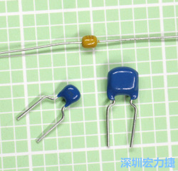
3.Single-layer ceramic capacitors are often used as bypasses, and are also suitable for use in high-frequency or audio circuits. Ceramic capacitors are somewhat unstable at different temperatures, but NPO types are more stable, and multilayer ceramic capacitors are smaller than single-layer capacitors. For this reason, more and more people are starting to use it.
Farad
The storage capacity unit of a capacitor is a farad, and the general abbreviation is F. If a capacitor is filled at a potential difference of 1 volt and can concentrate 1 amp in 1 second, it has a capacitance of 1 Farad.
Because Farah is a large unit, almost all capacitors in electronic materials use microfarad (μF), nanofarad (nF) and picofarad (pF), usually Greek. The letter μ will be used to represent micro (one thousandth), but it will often be replaced by the English letter u. For example, 10uF and 10μF mean the same thing.
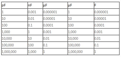
1F is equal to 1,000,000 μF, while 1 μF is equal to 1,000,000 pF. That is to say, 1 Farad is equal to 1 trillion picofarads, and the range between them is very wide. For the conversion between units, see Figure 16 "Pico Farad, Nefala and Microfarad Conversion", and nF is commonly used in Europe. Please refer to Figure 17 for the conversion of microfarad and fara. It is because the Farah unit is very large, and almost all the common electronic circuits are used in smaller units. You can see the conversion method between different units.
The unit of Nefala (nF) is more common in Europe than in the United States. 1nF may be expressed as 0.001μF or 1,000pF in the United States. Similarly, a 10nF capacitor will be expressed as 0.01μF, while a 0.1nF capacitor may be expressed as 100pF.
Circuit diagrams in European systems use numeric symbols instead of decimal points. For example, a 4.7pF capacitor may be written as 4p7, a 6.8nF capacitor may be represented as 6n8, and a 3.3μF capacitor may be labeled as 3μ3.