What is the function of the transformer?
The function of the transformer is to convert the voltage. After the AC is introduced from the input, various voltage values can be output.
Transformers vary in size from small acoustic impedance matching parts in audio equipment such as microphones to state-of-the-art power companies that weigh several tons of super monsters. Basically, as long as the required voltage is different from the voltage value of the city distribution, the electrical appliance will need a built-in transformer.
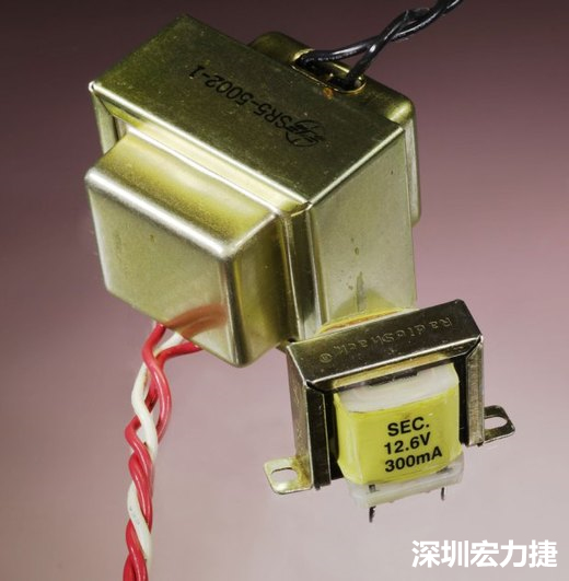
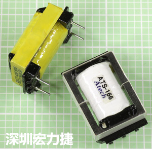
The latter transformer in the figure can be connected to 125V AC, which can output 36V AC, the current is 0.8A. The former one is a small transformer of Radio Shack, which supplies 12V AC at 300mA, in the absence of other load. Under the voltage, the voltage can actually reach 16V.
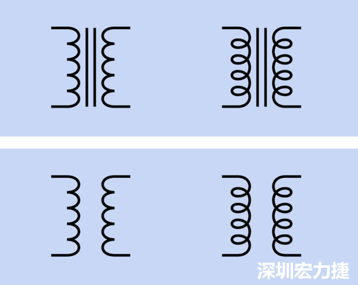
The circuit diagram of the transformer is as follows:
The left and right coils are drawn in different styles, but the functions are not different. Above: A transformer containing a magnetic core (which can be magnetized). Bottom: Hollow transformer (this type of transformer is rare because of its poor efficiency). Conventionally, the input of the transformer will be on the left side, through the main coil, and then from the right secondary coil. Generally, the number of turns of the primary coil and the secondary coil is different. If the primary coil is larger than the secondary coil, the output voltage value is decreased. If the number of primary coils is smaller than the secondary coil, the output voltage value is increased.
What is the principle of operation?
The following is a schematic diagram of the transformer construction:
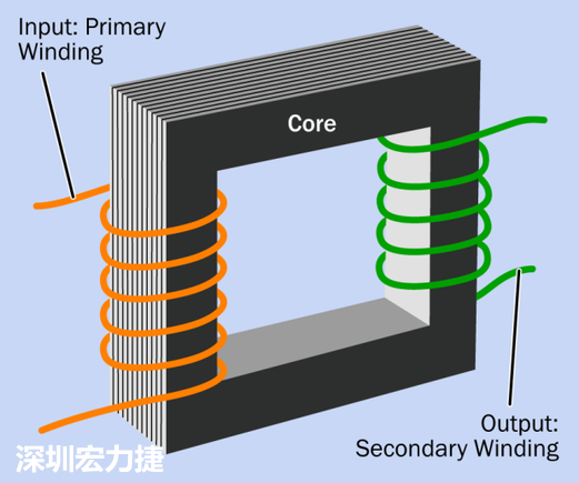
Input: number of main coil turns / output: number of turns of the secondary coil
If the current around the main coil (in orange) changes, it will cause the magnetic flux of the center steel plate to change. This change in magnetic flux will further generate current near the secondary coil (indicated by green), which is the current output from the transformer. (In actual cases, the number of turns of the enameled wire is tens of thousands, and there are different ways of assembling).
This process is called "mutual induction". If the secondary coil is in the vicinity of the secondary coil, current will be drawn from the primary coil, even if there is no circuit connection between the two coils, current will be generated.
In the ideal state, regardless of energy dissipation, the number of turns of the primary and secondary coils determines that the output voltage will be greater than, equal to, or less than the input voltage. If Vp and Vs represent the voltages of the primary and secondary coils, respectively, Np and Ns represents the number of turns of the primary and secondary coils, respectively, and their relationship can be expressed by the following formula:
Vp / Vs = Np / Ns
The rules of memory are simple, the fewer the number of turns, the lower the voltage value; conversely, the more the number of turns, the higher the voltage value.
If the output voltage is greater than the input voltage, it is called a step-up transformer; if the output voltage is less than the input voltage, it is called a step-down transformer.
Magnetic core
Many people think that the core is iron, but in fact, its material is high permeability silicon steel, and in order to reduce the energy loss caused by eddy current, the core is usually laminated, that is, layer by layer. The steel plates are separated by varnish or similar insulating material so that the eddy current is confined to the thickness of each layer of steel.
Because direct current causes magnetic saturation of the core, the transformer must accept alternating current or voltage pulses. The geometry and coil design of the transformer is designed to achieve the best results in the rated frequency range, voltage and current. If it is too far from these rated ranges, the transformer will be destroyed.
How many types of the transformer?
Here are some common transformer introductions:
1.Power Transformers
A common form is to screw it onto the base, mount it in the housing, or install an electronic part in the box with solder joints or connectors that connect the transformer to the power cord and the other end to the board.
2.Plug-in transformer
This type of transformer usually has a plastic casing that can be directly inserted into a wall socket. The shape is like a general AC transformer, but it can convert the input AC power into a DC output.
3.Isolation transformer
Also known as a one-to-one transformer, the ratio of the primary coil to the secondary coil of the transformer is exactly one to one, that is, the output voltage value and the input voltage value will be exactly the same. If the electronic instrument is inserted into the isolation transformer, it is equivalent to isolating the electronic instrument from the AC grounding system, which makes the risk of the electronic instrument running lower, because the instrument itself and the surface have negligible small potential difference, if the grounded object is touched at the same time. With the fire line inside, there will be no current flowing through the body.
4.Automatic transformer
The characteristic of this type of transformer is that only the coil of the output voltage is needed, and the mutual induction occurs between the coils of different layers, so that the input and the output generate a common connection. Unlike the double-coil transformer, the design of the double-coil transformer is to make the output The current is isolated from the input current. Self-tapping transformers are often used for impedance matching of audio lines. Typically, the output voltage is very small from the input voltage.
5.Audio transformer
When the signal is switched between circuits with different impedances, it may be weakened or interfered (the unit of impedance is ohms, but this is not the same as the unit of resistance of DC), because the impedance is related to reactance and capacitance, so it will follow the frequency. change).
If the input impedance of a device is small, it will try to sink current from the source. If the output impedance of the source is high, the voltage will drop drastically. Therefore, usually the input impedance of a device should be at least ten times the value of the output impedance of the drive. Passive components (resistors and / or capacitors and / or coils) can be used to adjust the impedance value, but in some cases, a small transformer would be a better choice.
6.Split coil transformer
The primary and secondary coils of such a transformer are adjacent to each other in order to minimize the degree of capacitance coupling.
7.Embedded transformer
The area may be less than 0.2 square feet, which is usually used to adjust the impedance value, twist the wire and filter the noise.
How about the numerical value?
When selecting a power transformer, the power load capacity should be considered first. This capability index can be the product of voltage and current (Volts x Amps, expressed in VA). Note that VA and watt are different concepts. Used in the DC circuit, it can be measured immediately; in the AC circuit, the voltage and current are constantly oscillating. Therefore, VA indicates the apparent power of the circuit, and the reactance should be taken into consideration.
The relationship between VA and Watt varies with different instruments, but in the worst case, it can be expressed by the following formula:
W = 0.65 VA (approximate)
In other words, the average power from the transformer should usually be greater than two-thirds of the VA.
Transformer specifications usually indicate input voltage values, output voltage values, and part weights. These concepts should not require much explanation. It is worth mentioning that the transformer's coupling must take into account the input and output impedance values.