What are the procedures of AD(Altium Desinger) in PCB layout ?
The first thing of the AD(Altium Desinger) PCB layout is to set the appropriate documentation options before drawing the schematic. As the following steps:
1. Select design > document options, document options from the menus menu and the dialog box appears. With wizard settings, you now only need to set the chart's size only to a 4. 4 for the only settings that change the size of the layer. In the sheet options option, find the standard styles option. Clicking on the next step will list a number of chart layers.
2. Select a 4 format and click ok. Close the dialog and update the chart layer size.
3. Remake the document to fit the size of the display by selecting view > fit document. In altium, menus can be activated by setting hotkeys. Any submenu has its own hotkey to activate.
For example, the previously mentioned view > fit document, can be achieved by pressing the v and d keys. Many submenu, such as eidt > deselect, can be implemented directly with a hotkey. To activate eid > deselect > all on current document, simply press the x hotkey and press s hotkey.
The following describes the overall configuration of the circuit schematic.
1. Select tools > schematic preferences, to open the Circuit schematic preference preferences dialog box. This dialog box allows users to set preferences for all schematic configuration parameters for the Global Bureau and for all schematics.
2. In the tree to the left of the dialog box, click schematic-default primitivesto activate and enable the permanent option. Click ok to close the dialog box.
3. Before you start designing the schematic, save the schematic and select file > save [shortcut: fins].
Drawing Circuit schematic Diagram of ad pcb Design
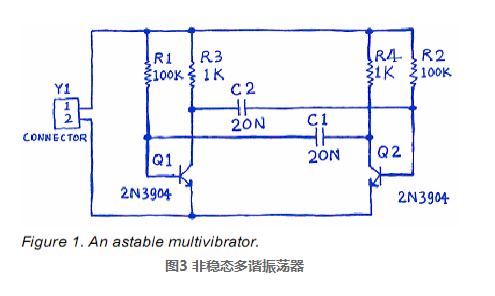
You can start drawing schematic diagrams next. This chapter uses the circuit diagram shown in figure 3 as an example. This circuit is composed of two 2n3904 transistors unsteady state multivibrator.
How can we design load components and Libraries for AD PCB?
Altium Designer provides a powerful library search function in order to manage a large number of circuit identifiers. Although the components are in the default installation library, it is important to know how to search the components from the library. Follow these steps to load and add the libraries required for figure 3 circuits.
First, let's look for a Triode with a 2n3904 model.
1. Click on the libraries tab to display the library panel, as shown in figure 4.
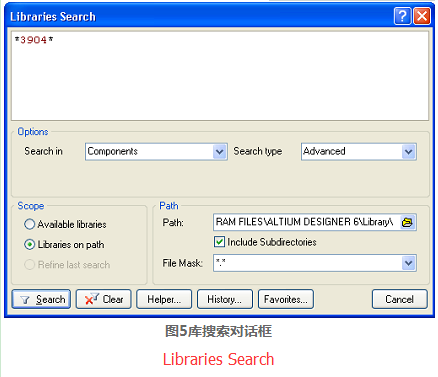
2. Click the search in button in the library panel or open the libraries search dialog box by selecting tools > find component, as shown in figure 5.
3. For this example, you must make sure that the search in the options setting is set to components. com. Different options are used for library searches.
4. You must ensure that scope is set to libraries on path and that path contains the correct path to connect to the library. If the default path is used when installing the software, the path will be library. You can change the path of the library folder by clicking the File Browse button. For this example, you also need to make sure that the include subdirectories complex box is checked.
5. To search for all 3904 indexes, enter 3904 in the search field of the library search dialog. Use * tags to replace different prefixes and suffixes used by different manufacturers.
6. Click the search button to start the search. After the search starts, the search results are displayed in the library panel.
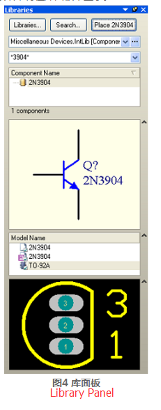
7. Click on the component named 2n3904 in the miscellaneous devices.intlib library and add it. This library has all the emulated bjt Triode element identifiers.
8. If you select a component that is not installed in the library, the installation library will be prompted before using the component to draw the circuit diagram. Because miscellaneous devices is installed by default, the component is available.
There is the option to add a library in the top drop-down list of the library panel. When you click on the name of a library in the list, all components in the library are displayed below. Components can be loaded quickly through component filters.